GK MB150S no sound but direct out works

I guys,
I have an issue with my amp that after a few minutes of playing i get no sound on the speaker and no sound on the external speaker but i still have the signal on my direct out (XLR) output. I tried to hit the amp with my hand just the test that there could be a loose joint and that helped first few times for about 10s. Now this doest help anymore. Do you have any ides of what could be the issue? And where to look at?
Thanks
 
Hi. I tried the instrument cable look trick but it didn't help. In the end I was using the bass amp with the XLR output for few gigs. Now the XLR output isn't working any more. Is there a schematic or a document which i can follow and try to debug my issue using volt meter? If it helps I can borrow oscilloscope. Thanks
 
Hi. I tried the instrument cable look trick but it didn't help. In the end I was using the bass amp with the XLR output for few gigs. Now the XLR output isn't working any more. Is there a schematic or a document which i can follow and try to debug my issue using volt meter? If it helps I can borrow oscilloscope. Thanks

Use proper caution and small mistakes can easily cause massive damage, but these docs may be of help. I included the Owner's Manual if yours was misplaced.
 

Attachments

  • MB150S-III Pre-Amp Board.pdf
    2.5 MB · Views: 8
  • MB150S&E-III Power Amp Board.pdf
    2.4 MB · Views: 7
  • MB Series OM.pdf
    1.7 MB · Views: 6
A voltmeter will not be the only tool you need, you will need a scope AND the knowledge to understand how the amp is supposed to work before you will be able to identify the fault(s). The two tier rail switching can be very tricky to understand and identify faults on, what appears obvious is anything but obvious once global feedback has its way with you.
 
  • Like
Reactions: WRM and B-string
I almost remember a CFM with these. It is lost in a fog and possibly miss-filed.
If the OP looks at the docs and they look like ancient Sanskrit, please stop and go no further. It is way too easy to turn a small problem into a footstool.
 
I just got one very recently, and I forgot how amazing these little amps are. I went from picking it up, straight to the jazz trio, and it was literally some of the best tone I've gotten from a live low volume amp. It's own thing, for sure! I love mine, and I hope you get yours ironed out soon with a good qualified tech!
 
Use proper caution and small mistakes can easily cause massive damage, but these docs may be of help. I included the Owner's Manual if yours was misplaced.
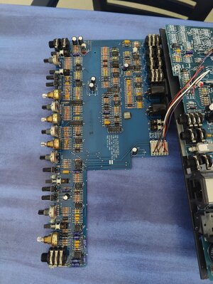
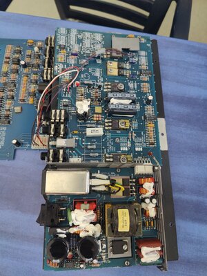
Does anyone has a shematic for the preamp MB150E? Here are photos of my setup.
 

Attachments

  • IMG20240923140810.jpg
    IMG20240923140810.jpg
    7.3 MB · Views: 1
  • IMG20240923140807.jpg
    IMG20240923140807.jpg
    8.3 MB · Views: 2
taking another look...all of the mosfets look like that. i can't believe GK would leave solder joints looking like this. maybe someone tried replacing all of them? the solder joints look dirty AF
1727122385380.png


this looks awful as well. not factory specs...

kgb
 
Except that none of these parts in your pictures are MOSFETs except one.

Something to be aware of, this version does not look like any MB-150E or S power supply that I have ever seen. That's an early SMPS that proved to be unreliable and was later changed to be a line frequency supply. What you have has already been screwed around with, you are missing one of the switching MOSFETs!

IMO, you might want to cut your losses on this one, it may be that there is additional damage to the power amp that caused the failure of the SMPS.
 
  • Like
Reactions: NitroBobby
ok....the first picture, i thought, was a MOSFET. i was stating that the other components of similar construction in the original picture all have dirty/overheated solder joints. if they are not MOSFETs, then i incorrectly identified them. that's on me.

the second picture, not likely a MOSFET or any transistor based on only having 2 pins, also has sloppy soldering. Diodes in a bridge rectifier circuit perhaps? (D538 & D53x)

in any case, they look to be not the original parts or someone did a lousy job trying to fix this board.

kgb
 
Last edited:
ok....the first picture, i thought, was a MOSFET. i was stating that the other components of similar construction in the original picture all have dirty/overheated solder joints. if they are not MOSFETs, then i incorrectly identified them. that's on me.

the second picture, not likely a MOSFET or any transistor based on only having 2 pins, also has sloppy soldering. Diodes in a bridge rectifier circuit perhaps? (D538 & D53x)

in any case, they look to be not the original parts or someone did a lousy job trying to fix this board.

kgb
There are a whole bunch of things that do not make sense on this, there are diodes and bipolar transistors shown which are correct, put the high voltage rail commutator switch(es) (which may be MOSFETs) are not correct and the original parts are missing. Once I see this, the next question I always ask is "what else has been screwed with?".

The parts labeled MOSPEC are bipolar parts, the brand is MOSPEC and they are part of the power amp, not the power supply.
 
  • Like
Reactions: NitroBobby