Jazz Bass pickups wiring problem

Nov 26, 2013
11
1
4,551
50
France
Hello,

I have a US Jazz Bass Plus from '92 and recently decided to have it passive. I thought that the Volume-Tone Volume-Tone thing would be good for me and decided to go this way.

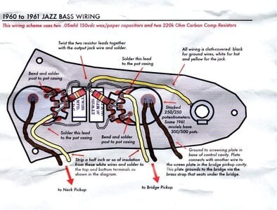
I come here because I have trouble, I did try both the RobbieK schematic and the Fender original (but with the 15K resistors) but I have almost no sound with both volume up, a little bit more with one not all the way up and the tone controls don't seem to really work... or on the volume !

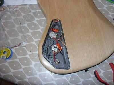
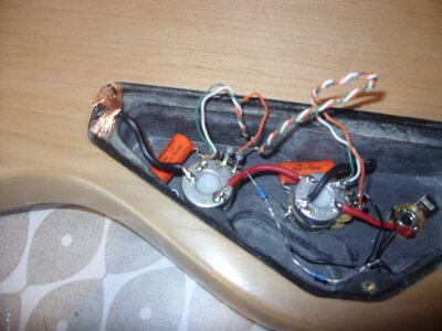
I tried to take pics but it's a little blurry, I hope you can see the mistakes.

I did at first try with red and green wires to the ground of the pot and using white wire as the hot one... same problems.
The capacitor is soldered from the ground post of the lower pot (the right one) to the casing of this lower pot. I didn't solder casing of the lower to the casing of the upper as it seems they are already connected.

The pickups are Fender Lace Sensor.

Should I sold the green wire directly to the ground output ?

Thanks for any advice and comments.
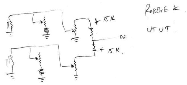
RobbieK VTVT.jpg FenderJVVTT.jpg SDC11423.JPG SDC11429.JPG
 
Those resistors are touching the shielding paint & leaking your signal to ground.
IMHO you should can the resistors idea & just turn down the volume of each pickup if you want individual treble cut (tone) controls for each pickup.
Turning those down just a little accomplishes the same thing.

or you can leave one pickup with both controls dimed & dial in what you want on the other pickup
 
Those 15K resistors are supposed to be part of an active circuit. Resistors in a passive circuit should be more like 250K-500K.

You are not understanding the purpose of the resistors in this scheme.

They are summing resistors that are there to provide isolation of the pickups. If you used a 250k-500k resistor, you would lose a lot of output. This is meant to be an improvement on the '60s stacked Jazz bass scheme.
 
Thanks everyone for those replies.

Unfortunatly I still have problems, I isolated the resistors but still volume issues. Then I saw that in the "'62 AMERICAN VINTAGE JAZZ BASS 0190209 CONTROL ASSEMBLY " there was a wire between input and output of the tone potentiometer so I did that but still the same. I also tried to change the resistors values and even rewire everything without resistors but I still have the volume going away when both volume knobs are up. When I turn back a little one then the volume comes back.

I think I did wire everything well but perhaps there is something wrong with those pickups in that configuration ? They have three wires, red, white and green and are used in the original way both in active or passive way.

Perhaps I need more electronics knowledge to make them work in a passive way.

Does anyone know if those pickups can be use as passive ones without changing the schematics ?
 
  • Like
Reactions: Killed_by_Death
You are not understanding the purpose of the resistors in this scheme.

They are summing resistors that are there to provide isolation of the pickups. If you used a 250k-500k resistor, you would lose a lot of output. This is meant to be an improvement on the '60s stacked Jazz bass scheme.
You're right, I didn't understand. Mine was a knee-jerk response based on previous discussions. I've always read that resistors that low were associated with active circuits. I understand the difference between 250K and 500K resistors in a passive circuit, but not much beyond that.
 
I finally found the problem and I still don't know if it's a common thing.

One of the pickups has to be wiring with the red wire with the green to the earth and the second with the white and the green to the earth. I can do that with one or the other and it works but both wired the same way and it doesn't work anymore.

One other surprise is that the neck pickup has less output that the bridge one, don't know if it's to make them more balanced. I didn't noticed it previously as it was a blended pot but I was always turning the pot slighly more toward the neck PU, I know why now.

Anyways, the 15K resistors work fine in this circuit and the drop off in output is close to insignifiant.