P-J wiring for V-V-T and 4-way P-J-Series-Parallel configuration

Nov 21, 2017
64
27
4,531
I have seen all related posts about P-J wirings but I am a bit confused and would like some help with the following:

1. So for the V-T option a regular Telecaster 4-way switch is suitable for P-J-Series-Parallel selection and I guess the wiring is similar to that of Telecaster. Is this correct?

2. For V-V-T what is the correct 4-way switch to get? I am confused regarding the number of poles needed to make it work. I saw in another post the attached diagram by user "line6man". Is this the correct diagram for this case?
4 way rotary switch.jpg
3. V-T with 4-way switch versus V-V-T with 4-way switch. What are the differences apart from the flexibility on controlling the volume separately?
 
1. Yes.

2. That is not a suitable diagram for VVT wiring. The switch has one output, so there cannot be two volume pots.

3. The simplest schemes are usually the most practical, so it would be best to stick to a single volume pot. Additionally, that lightens up the load on the pickups that comes from having pots in the circuit.
 
1. It's more than similar. Any instrument with two pickups and a 4-way switch diagrams out to be exactly the same.

2. There isn't just one way to do this. Of all the various 4-way switches out there, the 4-way Tele blade switch is by the easiest to use because it's large, is easy to check visually and has a nice tactile feedback. However, it requires a blade route, which most basses, for whatever reason, don't have, but if you can make one, it's obviously the one to use.

A rotary switch is the second best option, but verify that you have enough room for all of the wiring, which can get pretty large. A 4-position 4-pole rotary switch used to be pretty available from guitarelectronics.com, but I haven't seen it available recently. There might be a switch on DigiKey or Mouser that works. You can use a 5-position 4-pole rotary switch, in the mean time, usually sold as a PRS style switch. However, given that it's a 5-position, you either duplicate one position, or you can add another position, like the Bill Lawrence half-out-of-phase, or anything you can draw, really. If you want to work on a fun electronic puzzle, drawing a perfect 24-pole switch scheme can be a really rewarding exercise. I've done it before and it was well worth it. But it's not for the faint of heart.

Anyway, the diagram can be adapted for V-V-T by placing a volume knob where the neck and bridge pickup inputs are, and by connecting the master tone to where the output to the switch is, and then the output goes straight to jack. This also inadvertently creates what's known as 50s wiring, in which there is volume knob as the tone knob is turned down, but you retain more brightness as the volume knob is turned down.

3. V-V-T makes for some difficulty 4-way series-parallel wiring unless you have some good way of bypassing the second volume knob in series, which may be possible by redrawing the above diagram, but I've never tried to draw it myself. I say this because V-V-T was supposed to work with reversed volume knobs connected simply in parallel, no switch. But if you're using a switch, it's better to use regular volume knobs (like a Les Paul) with its output going to the switches, as that has better behavior when turning down, and then the second volume knob starts doing weird things when the pickups are in series, where it becomes what people call a spin-a-split, and it's not really a volume knob anymore, like you're just adding a little bit of the second pickup to the first pickup's output. So that could be kind of cool. But you have to understand that this is how it will work, and it might be too sophisticated for some users.

V-T with a 4-way, meanwhile, is extremely easy.

Lastly, you can use a V-switch-T with a regular 3-way switch (or an ungrounded blend) and use a push-pull parallel-series for either the V or the T, and when the series is pulled, the switch (or blend) would have no effect at all. This is quite easy to do, easy to use, and requires no blade switch routing and is very small under a control plate, whereas a rotary can be rather ginormous and cause problems in crowded control cavities. You can also use a toggle instead of a push-pull for the parallel-series, but that requires another hole, but that's a simple one to drill, vs. a blade switch which is quite difficult for a lot of people.
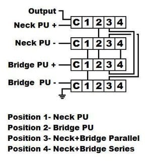
 
1. Yes.

2. That is not a suitable diagram for VVT wiring. The switch has one output, so there cannot be two volume pots.

3. The simplest schemes are usually the most practical, so it would be best to stick to a single volume pot. Additionally, that lightens up the load on the pickups that comes from having pots in the circuit.
Thanks for your reply. I am only thinking that with one Vol you can't have the option of rolling back the Vol of one of the PU while having the other at full volume etc. If keeping the V-V-T what would you suggest: a push/pull for series/parallel or a 3-way switch for selecting PU?

Actually I think I mostly prefer having the options P only - Series - Parallel with V-V-T. Would that be possible/easier to make? Any thoughts on this?
 
Last edited:
1. It's more than similar. Any instrument with two pickups and a 4-way switch diagrams out to be exactly the same.

2. There isn't just one way to do this. Of all the various 4-way switches out there, the 4-way Tele blade switch is by the easiest to use because it's large, is easy to check visually and has a nice tactile feedback. However, it requires a blade route, which most basses, for whatever reason, don't have, but if you can make one, it's obviously the one to use.

A rotary switch is the second best option, but verify that you have enough room for all of the wiring, which can get pretty large. A 4-position 4-pole rotary switch used to be pretty available from guitarelectronics.com, but I haven't seen it available recently. There might be a switch on DigiKey or Mouser that works. You can use a 5-position 4-pole rotary switch, in the mean time, usually sold as a PRS style switch. However, given that it's a 5-position, you either duplicate one position, or you can add another position, like the Bill Lawrence half-out-of-phase, or anything you can draw, really. If you want to work on a fun electronic puzzle, drawing a perfect 24-pole switch scheme can be a really rewarding exercise. I've done it before and it was well worth it. But it's not for the faint of heart.

Anyway, the diagram can be adapted for V-V-T by placing a volume knob where the neck and bridge pickup inputs are, and by connecting the master tone to where the output to the switch is, and then the output goes straight to jack. This also inadvertently creates what's known as 50s wiring, in which there is volume knob as the tone knob is turned down, but you retain more brightness as the volume knob is turned down.

3. V-V-T makes for some difficulty 4-way series-parallel wiring unless you have some good way of bypassing the second volume knob in series, which may be possible by redrawing the above diagram, but I've never tried to draw it myself. I say this because V-V-T was supposed to work with reversed volume knobs connected simply in parallel, no switch. But if you're using a switch, it's better to use regular volume knobs (like a Les Paul) with its output going to the switches, as that has better behavior when turning down, and then the second volume knob starts doing weird things when the pickups are in series, where it becomes what people call a spin-a-split, and it's not really a volume knob anymore, like you're just adding a little bit of the second pickup to the first pickup's output. So that could be kind of cool. But you have to understand that this is how it will work, and it might be too sophisticated for some users.

V-T with a 4-way, meanwhile, is extremely easy.

Lastly, you can use a V-switch-T with a regular 3-way switch (or an ungrounded blend) and use a push-pull parallel-series for either the V or the T, and when the series is pulled, the switch (or blend) would have no effect at all. This is quite easy to do, easy to use, and requires no blade switch routing and is very small under a control plate, whereas a rotary can be rather ginormous and cause problems in crowded control cavities. You can also use a toggle instead of a push-pull for the parallel-series, but that requires another hole, but that's a simple one to drill, vs. a blade switch which is quite difficult for a lot of people.

Thank you very much for your extensive response. Regarding the last thing you mention. Is it doable having both a push-pull for series-parallel and a 3-way PU selector switch? Do you have in mind a wiring diagram or feedback on this option?

I think I prefer having two Vol but I am not sure if I should go for a series-parallel option or PU selector if not possible to have both. In fact the options I am mostly interested having are: P only - Series - Parallel, not so much J only. Is such wiring possible/easier to make?