Strange wiring, I need help

What should I do with it?

  • Replace electronics but try to discover and keep the original functioning.

    Votes: 0 0.0%
  • Hang it on the wall and don't bother ever playing it. it looks cool enough.

    Votes: 0 0.0%

  • Total voters
    1
Can anyone help me make some sense of this?

I've had this bass for years, and I fineally want to do something with it. it's super old, beat up and some parts seem very cheap. but it looks cool and when I can get a sound out of it, I quite like the tone...

I only recently got into wiring and electronics so I don't understand much, but this one just seems too odd. I want to put new electronics in or just replace some parts because a bunch of things don't work properly.

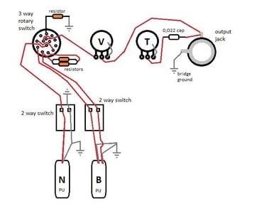
what seems weird to me is that the neck pickup has one lead and the bridge 2. then they bot go straight into a 2 position switch. right now the bass only makes sound when the 2 2-way selector switches are like on the pickture, one up and one down. any other combination and I get no sound at all. after the 2-way switches the wires go into a 3 way selector. I get sound from all 3 options but only one gives a decent volume, in the other 2 positions the sound is very weak.

The 3-way selector is a type that I don't have any experience with, but it does seem odd that there are 2 capacitors wired simultaniously in the same spot. after the 3-way there is a volume, no problems there, then is the tone, no problems here either. But I don't understand how there is nothing connected to the tone pot except a capacitor between the tone and the output jack.

I bought a bunch of cheap electronics and parts and I got parts from other basses as well, I don't need to make this particular bass into one I can gig with, but it would be nice if I could get it to at least work proparly and be decent enough to jam with every once in a while.

If anyone understands some of this wiring, please help me out, I would be super grateful.
I can always post more or better pictures if needed.

Thanks

Nathan
IMG_20180506_132622254.jpg
IMG_20180506_132750440_HDR.jpg
IMG_20180506_132631392.jpg
IMG_20180506_132732284.jpg
IMG_20180506_132823885.jpg
IMG_20180506_132834141.jpg
IMG_20180506_132742622.jpg
 
From what I can tell, someone's been in here before you.
The rotary switch doesn't look stock, looks like something Radio Shackish.
Wonder if it was added later?
If this is an added switch, maybe it was what was in the junk box and not all positions were meant to do something. Or the switch just has some bad contacts.

The two "simultaneous capacitors" actually appear to be two resistors wired in Paralell to achieve a certain resistant that could not be achieved with a standard value. They look like two 39K (Orange, white, orange?) which would work out to be 19K. The other resistor (red, red, orange) is 22K.
Maybe the other person needed two 22K resistors and didn't have them in the drawer so made something close using two 39Ks in Paralell?

The only cap that appears to be in there is the gray one down by the Jack, .022 ufd?

Not sure why those resistors are in there except to balance out differences that happen when switching and so you can switch without sudden large changes in volume.

It seems odd to see resistors like this in a passive bass.

What would I do?
If the goal is to just get this cool old bass back to playing condition
I'd chuck all the switching and just do a simple VVT setup.
Replace the pots, the Jack if it seems spongy, and maybe the tone cap if you don't like how it sounds with that value.

The .022 ufd seems a bit low for bass, but that also depends on the other components and desired tone control action.
 
Last edited:
From what I can tell, someone's been in here before you.
The rotary switch doesn't look stock, looks like something Radio Shackish.
Wonder if it was added later?
If this is an added switch, maybe it was what was in the junk box and not all positions were meant to do something. Or the switch just has some bad contacts.

The two "simultaneous capacitors" actually appear to be two resistors wired in Paralell to achieve a certain resistant that could not be achieved with a standard value. They look like two 39K (Orange, white, orange?) which would work out to be 19K. The other resistor (red, red, orange) is 22K.
Maybe the other person needed two 22K resistors and didn't have them in the drawer so made something close using two 39Ks in Paralell?

The only cap that appears to be in there is the gray one down by the Jack, .022 ufd?

Not sure why those resistors are in there except to balance out differences that happen when switching and so you can switch without sudden large changes in volume.

It seems odd to see resistors like this in a passive bass.

What would I do?
If the goal is to just get this cool old bass back to playing condition
I'd chuck all the switching and just do a simple VVT setup.
Replace the pots, the Jack if it seems spongy, and maybe the tone cap if you don't like how it sounds with that value.

The .022 ufd seems a bit low for bass, but that also depends on the other components and desired tone control action.

Thanks, that was helpful. If I can find a similar rotary switch I might buy that and replace the one that's in there cause it looks old, I also bought some normal potentiometers, new DPDT switches, and a 0.047 capacitor that I'll probably put in there instead of the 0.022

The goal is indeed to get it in playing condition, but another equally important goal is to learn. Like I said, I'm new to electronics, but I really wanna learn more about bass guitar wiring. if I just put a VVT circuit in there I'm not really learning anything I don't know yet...
 
Last edited:
Thanks, that was helpful. If I can find a similar rotary switch I might buy that and replace the one that's in there cause it looks old, I also bought some normal potentiometers, new DPDT switches, and a 0.047 capacitor that I'll probably put in there instead of the 0.022

The goal is indeed to get it in playing condition, but another equally important goal is to learn. Like I said, I'm new to electronics, but I really wanna learn more about bass guitar wiring. if I just put a VVT circuit in there I'm not really learning anything I don't know yet...
OK. Nothing like challenging yourself and having a practical application to test it out.
I guess the interesting thing would be to re-create some, or all of the switching, but loose the resistors.
In a passive bass, using resistors just to balance things out when switching may also just cut volume or be a tone suck.
One thing to try, just temporarily is to just wire the pickups directly to the Jack. No resistors, not pots, no caps, just raw pickups to the amp. It will really open your eyes as to the potential. Of course you'll eventually add in vol and tone pots. But it sure might make you think about trying to minimize the stuff you throw in there.
That's a good point you make. I'll most likely replace the pickups though, since the outer shell is a bit broken and makes a weird noise everytime I accidentally touch it while playing. but maybe it's better to look for other casings and leave the pickup...
either way I'll definately test the new and old ones straigt to the output jack (I bought new ickups in the same style but not yet certain wich bass to use them on)
 
  • Like
Reactions: Old Garage-Bander
Can anyone help me make some sense of this?

I've had this bass for years, and I fineally want to do something with it. it's super old, beat up and some parts seem very cheap. but it looks cool and when I can get a sound out of it, I quite like the tone...

I only recently got into wiring and electronics so I don't understand much, but this one just seems too odd. I want to put new electronics in or just replace some parts because a bunch of things don't work properly.

what seems weird to me is that the neck pickup has one lead and the bridge 2. then they bot go straight into a 2 position switch. right now the bass only makes sound when the 2 2-way selector switches are like on the pickture, one up and one down. any other combination and I get no sound at all. after the 2-way switches the wires go into a 3 way selector. I get sound from all 3 options but only one gives a decent volume, in the other 2 positions the sound is very weak.

The 3-way selector is a type that I don't have any experience with, but it does seem odd that there are 2 capacitors wired simultaniously in the same spot. after the 3-way there is a volume, no problems there, then is the tone, no problems here either. But I don't understand how there is nothing connected to the tone pot except a capacitor between the tone and the output jack.

I bought a bunch of cheap electronics and parts and I got parts from other basses as well, I don't need to make this particular bass into one I can gig with, but it would be nice if I could get it to at least work proparly and be decent enough to jam with every once in a while.

If anyone understands some of this wiring, please help me out, I would be super grateful.
I can always post more or better pictures if needed.

Thanks

Nathan
View attachment 3007711 View attachment 3007712 View attachment 3007717 View attachment 3007719 View attachment 3007722 View attachment 3007714 View attachment 3007720
It took me a long time to make but was kinda fun, if only I understood what everything was supposed to do... the grounding was a but hard to follow because it looks like just everything is grounded to everything, grounding wire everywhere, but I guess that can't hurt.
 

Attachments

  • wiring diagram NN bass.jpg
    wiring diagram NN bass.jpg
    30.7 KB · Views: 25
It took me a long time to make but was kinda fun, if only I understood what everything was supposed to do... the grounding was a but hard to follow because it looks like just everything is grounded to everything, grounding wire everywhere, but I guess that can't hurt.
Do you have a VOM (multi-meter)?
It might help you understand it better if you could parse out what the three switches are doing.
As is, the two way switches appear to turn off the pickups by shorting them out.
That would be a weird way of doing things.
 
Do you have a VOM (multi-meter)?
It might help you understand it better if you could parse out what the three switches are doing.
As is, the two way switches appear to turn off the pickups by shorting them out.
That would be a weird way of doing things.
I ordered a multimeter online, should be here in about a week. why would you want to individually turn off your pickups? If that's the case I won't be recreating that, I'll have to look for something else to do with the switches.
 
Do you have a VOM (multi-meter)?
It might help you understand it better if you could parse out what the three switches are doing.
As is, the two way switches appear to turn off the pickups by shorting them out.
That would be a weird way of doing things.
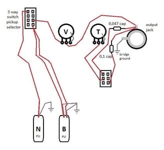
Would this be possible to do? in case I completely misunderstand; the idea was to use a 2 way switch to toggle between having a 0,47 and a 0,1 capacitor. (I messed up the PU selector, but that's besides th point so I didn't bother correcting)
 

Attachments

  • wiring diagram NN bass mods.jpg
    wiring diagram NN bass mods.jpg
    28.1 KB · Views: 63
Would this be possible to do? in case I completely misunderstand; the idea was to use a 2 way switch to toggle between having a 0,47 and a 0,1 capacitor. (I messed up the PU selector, but that's besides th point so I didn't bother correcting)
Yes it is possible with a SPDT switch to switch between having one or the other tone cap in circuit.
You can also have one .047 in circuit all the time and use a simpler SPST switch to add a second .047 in parallel with the first.
The two caps in parallel would equal 0.94 which is close enough to 0.1 that it won't be noticeable.
Besides, most cap tolerances are on the order of 20%. It's not like the values you use are critical. That way, if you have a switch failure, you always have at least one tone cap in circuit.
 
  • Like
Reactions: Nathanvleugels
Yes it is possible with a SPDT switch to switch between having one or the other tone cap in circuit.
You can also have one .047 in circuit all the time and use a simpler SPST switch to add a second .047 in parallel with the first.
The two caps in parallel would equal 0.94 which is close enough to 0.1 that it won't be noticeable.
Besides, most cap tolerances are on the order of 20%. It's not like the values you use are critical. That way, if you have a switch failure, you always have at least one tone cap in circuit.
Awesome,
thank you so much for all your help! I know what to do now