1961 B-15N, new problem with my power tubes and sparking...

May be a dumb question, but I've always done measurements before with power tubes installed. Heard of people measuring voltage at the socket, but with tubes out. Measure with tubes in or out? Or both?

Without the tubes as a first step for safety. Some Ampeg schematics have reference voltages on them, this is with the tubes installed. Check your schematic. The attached 1960 has some voltages, the 1961 doesn't. Note that is with 117VAC, your line voltage may be higher which will affect your readings. This is where a Variac can come in handy.
 

Attachments

Last edited:
  • Like
Reactions: Hoochie Coochie Man
Tubes in the sockets. Out won't tell you much, except what the no-load B+ voltage is.

Not true.

Measuring voltages without the tubes allows you to confirm the presence of the correct voltages being present BEFORE installing a set of tubes. I like to know if the screen voltage is correct and where I expect, that the bias voltage is in the correct range and on the correct pin, and that there are no unexpected voltages present. This information, plus verifying that the screen, grid and any cathode resistors are of the expected values go a long way towards a professional approach, as well as protecting a potentially expensive set of new tubes.
 
This is all great info... many thanks!

I will try and get this done this evening and report back my results. I've already put the appropriate resistors in my Mouser cart, so ready to order if needed.

I'll start with power tubes out (leaving preamp tubes and PI in place) and then move on to my current (and suspect) pair of 6L6GC installed, and those readings.
 
One more thing to check: intermittent speaker connection. If vibration caused the speaker circuit to open while you were playing, you'd sure enough get some popping and sparking!

And... it might not be a bad idea to pick up a matched set of current production 6L6GCs. Won't cost too much, you can test without risking your valuable NOS tubes, and it never hurts to have spares.

The speaker is well connected, I checked that out already, it's good and solid.

Excellent idea on the 6L6GC... it reminded me that I may have a newer set of JJs tucked into the bottom of my Fender HRD, forgot about those!
 
I was under the impression that it was only one of the 6L6GC tubes that was flashing.

Is this correct?
Is it a gentle flash that just makes a low sparting sound or is it dramatic like a storm in the tube?
Does a crackling sound come out of the speaker when this happens?
When this happens is there a high pitched oscillation type sound that comes out of the speaker?

Yes, it was only one tube that did it. Since I couldn't replicate it, it never sparked again after I swapped them (then swapped back).

I wouldn't call it a gentle flash, more like an old zippo lighter right after a fresh flint is installed. Tiny lightning bolts though, a bit more accurate. From mica area to getter discs? More or less?

And yes, crackling thru the speaker, no doubt. Kinda made me think I'd heard a bit of popping a few weeks ago, when I hit some heavy, open E notes on my P-Bass... but it didn't do it after that, so I ignored it, until the flashes I saw yesterday.

No high pitched oscillation, just crackling, but sharp.

It definitely wasn't a soft spark, more like there was a miniature Frankenstein's lab set up on the top mica level of my 6L6. It was very brief, and stopped for the few seconds that I quit playing before I shut it off. Was not sparking until I was pumping some strong notes thru it.
 
Not true.

Measuring voltages without the tubes allows you to confirm the presence of the correct voltages being present BEFORE installing a set of tubes. I like to know if the screen voltage is correct and where I expect, that the bias voltage is in the correct range and on the correct pin, and that there are no unexpected voltages present. This information, plus verifying that the screen, grid and any cathode resistors are of the expected values go a long way towards a professional approach, as well as protecting a potentially expensive set of new tubes.
With fixed bias, measuring the grid pin without the tubes installed is a useful test.
With cathode bias, there's no way to determine the bias voltage without the tube passing current. This one test will offer much information as to what's going on in this instance.

This is why I distinctly mentioned to not install a new set of tubes until some preliminary tests are made.
 
Okay, here is what I got when checking voltage (power on, standby off, speaker plugged in, guitar plugged in, volume at zero):

Cathode, Pin 8 = 32V (same on each tube)
Screen Grid, Pin 4 = 391V (same on each)
Plate, Pin 3 = 392V (same on each)
250ohm/10w Resistor = 33v on positive side, 0 on negative side

About right? Screen grid should be a tad lower (according to 1960 schematic), but not a huge difference.

Thoughts?

(Gonna go get these same readings for that B-18N also)
 
With fixed bias, measuring the grid pin without the tubes installed is a useful test.
With cathode bias, there's no way to determine the bias voltage without the tube passing current. This one test will offer much information as to what's going on in this instance.

This is why I distinctly mentioned to not install a new set of tubes until some preliminary tests are made.

Without the tubes installed, you better have zero volts on the grid. If you don't, I would immediately suspect the .02uF blocking caps. If one is shorted, I sure wouldn't want to discover this with a set of tubes present... could be responsible for the op's symptoms (if that's what's measured).
 
Yes, it was only one tube that did it. Since I couldn't replicate it, it never sparked again after I swapped them (then swapped back).

I wouldn't call it a gentle flash, more like an old zippo lighter right after a fresh flint is installed. Tiny lightning bolts though, a bit more accurate. From mica area to getter discs? More or less?

And yes, crackling thru the speaker, no doubt. Kinda made me think I'd heard a bit of popping a few weeks ago, when I hit some heavy, open E notes on my P-Bass... but it didn't do it after that, so I ignored it, until the flashes I saw yesterday.

No high pitched oscillation, just crackling, but sharp.

It definitely wasn't a soft spark, more like there was a miniature Frankenstein's lab set up on the top mica level of my 6L6. It was very brief, and stopped for the few seconds that I quit playing before I shut it off. Was not sparking until I was pumping some strong notes thru it.

That rules out some possibilities.

This leads me to wonder if the power tube socket contacts are properly tensioned. The tube should slide in and out of the socket with some resistance. If it slides too easily or if in doubt, the sockets should be re-tensioned. This has to be done very carefully.
 
I seem to recall tensioning a receptacle once; trying to recall how the little individual pin 'claws' lock in there. I'll see if I can figure it out. I suspect the same, since that particular octal socket feels the easiest to get the tube into and out of.

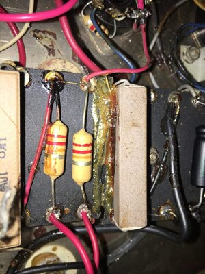
Another observation I had involves the attached image; there is an old repair to the original eyelet board, right at the suspect resistor. From what I can see, the solder joints are still fine, but I do wonder what might be affected on the underside, out of view. Isn't it true that those old eyelet boards are just a rigid place for soldering connections? There aren't any tracers or connections on the underside that would be affected by that crack, are there?

Fairly certain that board was cracked when the tech replaced the PT a long time ago. Then tried to repair it with epoxy, but tge repair didn't seem to hold up to well.
 

Attachments

  • IMG_3147.JPG
    IMG_3147.JPG
    210 KB · Views: 35
Last edited:
Use a needle or small jewelers screwdriver to carefully pinch the tube socket terminal contact so it will be a bit tighter.

The eyelet board is a parallel row of eyelets on a non conductive substrate. There are no traces on the substrate under the board.

I do see some things in the image that concern me. There shouldn't be any gunk between eyelets that can act to increase conductivity or capacitance.

Eyelets need to be cleaned so that you can inspect the solder joints. The black material on the eyelet on the left, for instance, should be cleaned up so that the joint can be inspected. You can use 99% isopropyl alcohol, available at a pharmacy, on Q-tips.

Many epoxies are electrical insulators and are non conductive, some are not though. I would remove a small amount of the epoxy around the eyelets. So that it is not in contact with ny of the eyelets.

It isn't unusual to find these boards in a bit of a mess and in need of a cleanup. Understandable for a 56 year old amp.
 
  • Like
Reactions: bobyoung53
Thanks, I'll give that a shot. Have got plenty of alcohol around, been using it to clean other stuff.

Some of that black goop appears to be from the cap that lost it's oil at some point. Some of the other goop looks like someone (Ampeg builder?) glued down many random spots of wire, I assume to keep them from moving about. Did Ampeg do that during their builds? Or was that just an over-zealous tech at some point, later on down the road?

Yes Ampeg did glue down some wires in the very early amps. Makes the amp more road worthy. I'd try to clean up anything that leaked out of a capacitor. It can be hard to get some of that stuff off.
 
That black paste from the capacitor is the electrolyte; it can conduct and should certainly be cleaned up. Acetone may help.
However, if there was cathode current leakage to ground bypassing the resistor, This would only lower the bias, and the tubes would pass more current, perhaps enough to damage them and/or the output transformer, but I doubt this would create any arcing.

Arcing is another story. This is caused by by excessively high voltages between the electrodes. Fender twins run the 6L6s pretty hard, with around 525 volts on some of the ones I've worked on, so we're talking voltages probably well in excess of a 1000V to create an arc between the electrodes internally. I've seen sockets that had carbon traces due to operating the amp without a load, that will continue arcing under normal operating parameters with a load connected. Usually the sockets have to be replaced outright. Because the arcing is taking place within one tube, there must be some back EMF off the output transformer creating these excessive voltages high enough to produce an arc, and the one arcing tube has a lower breakdown voltage compared to the other.

Check all your output transformer connections and the multipin plug for the speaker; the ground connection for the B+ is completed through this plug via the standby switch. This is to disable the B+ when this speaker plug is disconnected.

Another potential cause could be an intermittent tinsel lead on the speaker, or even the voice coil, if all the speaker wiring checks out fine.
 
Or simply mechanical damage inside the tube, reducing internal clearances resulting in flash over.

This is why determine the operating voltages are correct on each pin. If these are correct, and there are no other causes, it becomes (more) likely that it's just a tube defect.
 
Or simply mechanical damage inside the tube, reducing internal clearances resulting in flash over.

This is why determine the operating voltages are correct on each pin. If these are correct, and there are no other causes, it becomes (more) likely that it's just a tube defect.
That's entirely possible; it's a good idea to test the tubes first as a matter of course, but not everyone has a tube tester at hand. The crux of the issue is: Did a bad tube create the problems, or did problems within the amp cause the tube to go bad?

One thing that raises suspicion is the way the cathode bypass cap failed. Usually electrolytics dry up and loose capacitance with heat and time; a quiet death. Because this cap ruptured and leaked all the electrolyte paste makes me think this cap suffered extreme ripple, or excessive voltage, as would occur should the cathode resistor open up.
 
  • Like
Reactions: agedhorse