Double Bass Adjuster threads - above or below?

Beautiful 1/4-20 solid Brass adjusters from the mid 80's/early 90's. They were installed "threads down" as I recall.
They worked just fine, but were swapped out for some lighter adjusters on the advice of a Qualified Luthier.
Anybody want these?
Thx.
IMG_5538.jpg
 
Please tell me how you remove several mm of wood from the threaded side, drill a deeper hole and ……. I’ve been trying to find a way to do it.
Me, I'd hold the twist drill (tap drill) in a vise, slide the threaded hole over it, and then rotate the workpiece to deepen the tap drill hole. This way you have control of the alignment. Once you've deepened the tap drill as much as needed, then you chuck the workpiece in the vise, take the tap and thread it into the existing threads and then cut the new deeper threads. Especially in wood, with its weak nature, I'd consider using all three of the taps in the set - taper, plug, and if you really need it, bottom - but most threaded holes you probably don't need to bottom-tap.

For depths, consider that a taper tap has 5 threads of lead-in, a plug tap three, and the bottom tap aobut 1-1.5. So you have to allow at least one thread more than that to have some bottom clearance to your threaded component. If you bottom a threaded stud in a threaded wood hole, you'll probably just break the wood piece in two at the bottom of the hole. Or, if it's a crappy cast aluminum component with a whacking great porosity in it, you might well break the metal piece.

If you need to remove material from the surface that the threaded hole is in, I'd recommend deepening the threaded hole first and then machining down that surface, so you'll have more pilot length while you're working in the hole.
 
Beautiful 1/4-20 solid Brass adjusters from the mid 80's/early 90's. They were installed "threads down" as I recall.
They worked just fine, but were swapped out for some lighter adjusters on the advice of a Qualified Luthier.
Anybody want these?
Thx.
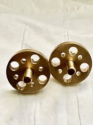
View attachment 7055079
I don't think those are one piece; I think those are two piece that've been joined. There's no way to have made those male threads that run out at the flat surface of the disk. A die has a couple threads lead in so there's always some incomplete threads, and you can't single point thread right up to a flat like that either. A quibble, but I believe those are two pieces, probably soldered together (and they'll never come apart).
 
  • Like
Reactions: Don Kasper
For that matter, if weight were a concern, why not drill a ring of holes in the disks to lighten them? Or turn a big honkin' face groove on the threaded side of the disk?
 
I don't think those are one piece; I think those are two piece that've been joined. There's no way to have made those male threads that run out at the flat surface of the disk. A die has a couple threads lead in so there's always some incomplete threads, and you can't single point thread right up to a flat like that either. A quibble, but I believe those are two pieces, probably soldered together (and they'll never come apart).
Yes...I may have been less than accurate in my choice of words. I meant "solid..." to mean "all brass". They are (each) made from 2 pieces of Solid Brass.
Thanks for the Righteous Quibble!
 
For that matter, if weight were a concern, why not drill a ring of holes in the disks to lighten them?
Challenge accepted.
They still are not "Light", but they are "less Heavy".
No CADCAM was used in the product modification below: (all analog layout and drilling.)
Thx.
IMG_5545.jpg

IMG_5548.jpg
 

Attachments

  • IMG_5545.jpg
    IMG_5545.jpg
    1.1 MB · Views: 2
Last edited:
Not at all... a "hole" is a negative space and is at or below the surface of the disk. There is no protruding edge to "catch on the wood...".
Yes? That's how I see it.
Thx.
right, but the argument (if there is one) would be that wood is slightly "squishy" and might bulge microscopically into the gaps

still, i see you nicely chamfered the hole edges and i'm pretty sure we're not supposed to be turning them under full string tension anyway

more importantly it looks super cool :D
 
  • Like
Reactions: Don Kasper
that wood is slightly "squishy" and might bulge microscopically into the gaps
I've not found bridge Maple wood to be at all "squishy"...(smiley face here)
Yes - I always release some of the string tension whenever I turn my adjusters. I think it's a good idea, and I've never experienced any binding issues, though other folks around here will adamantly insist on turning adjusters under full string pressure... (frowny face here)
IMFO, of course.
...and Thanks for your kind words and estute observations!
 
Last edited:
"Mine is a bit of an oddball as I have two-part adjusters. The wheel is separate from the threaded stud. So obviously the visible threads are below the wheel, but the threaded part doesn't rotate.

I just realized the Full Circle I just ordered relies on at least one of the two bridge components having threads in the wood. I don't know whether my bridge feet are threaded! The adjusters I have would work the same with unthreaded holes in both sides. I may be running down to the auto parts store and getting a Heli-coil kit."


One of the posts is threaded. The full circle will come with 2 adjusters so you can get rid of those 2 piece adjusters. Most people just glue the wheel to the shaft so they work normally. They aren't very good. You will be better off with one piece adjusters
Well, I took the thing apart, and got a bit of a surprise. Neither the upper part of the bridge NOR the foot is threaded! AND it's not 5/16-18 but rather M8 x 1.25!

Here's one of the feet with the separate adjuster wheel, as it came off the bass. You can see that obviously the upper surface of the wheel is what's supporting the upper part of the bridge, so it appears when installed as "threads down".

IMG_3682.JPG


Now where the surprise came was when I tried to remove the threaded stud from the foot; I thought I'd just be able to unscrew it. NOPE! If you look carefully you can see a little DOT on the wood just below where the stud goes in. That is actually the end of a small PIN which goes THROUGH the stud to keep it from turning:

IMG_3684.JPG


In the picture just above you can see the little hole in the wood, and the UNTHREADED part of the stud that goes into the wood. You can just see the hole in the stud. But here's a better photo:

IMG_3686.JPG


And here you can see the pin (made from a nail!) loosely started into the hole in the foot.

IMG_3687.JPG


So now I have to put a bushing on the unthreaded upper part of the Full Circle wheel/pickup (I already did this) and put a threaded insert into the foot (I've already ordered this). NOT the standard installation I was led to expect.

Has anyone else seen this particular configuration?