Friends, Luthiers, lend me your eyes (pickguard & PU design)

  • Like
Reactions: cdlynch
That's turning out really cool! :thumbsup:

Thanks in no small part to your help!

I'm gonna hafta do some spot soldering on the PG shielding, but I'm a little worried about melting and whatnot. I'll approach with a light touch. I seriously need to upgrade my soldering setup too. In the end, I'll be into this jalopy for around $1200 (over many years) and no one in their right mind would ever pay over $300 for it. Good thing I'm never selling. :)
 
  • Like
Reactions: JIO
I went with this pickup layout to match a Ric 4003, plus a J-ish bridge location, all on octave harmonics, and that's good enough for me. But out of curiosity I did a quick search for anything similar in the wild, and didn't find much.

Borisov Bas-1:
RussianBorisovBas1.jpg
Some PRS dealie:
prs3pu.jpg
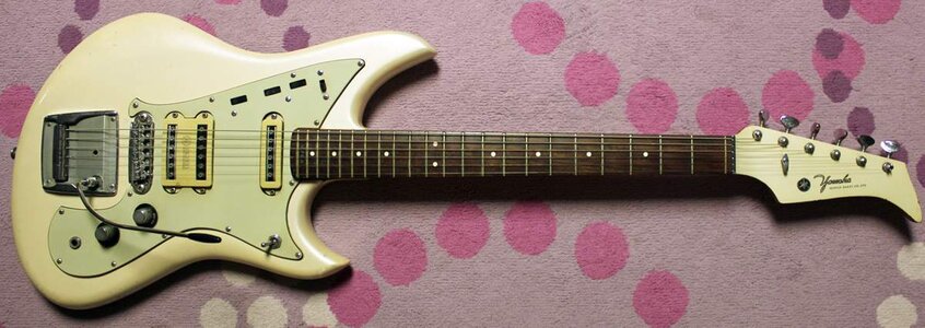
Yamaha SG-3:
1966YamahaSG-3.jpg

I didn't find any evidence of an SB-3 model, but I didn't look very hard. I derive no real meaning from this exercise, but google image searches are fun.

EDIT: Whoops!! I left out @Will_White's Fireman project!!! Sorry about that Will. But hey, great minds and all that... ;)
 
Last edited:
I'm cutting up some test plexi before transferring to the final guard, and I assume there's a much better/easier way, but this is how it's happening since I don't know what I'm doing. I measured and transferred switch and jack dimensions to the desired locations with ruler and awl, and now I'm painstakingly starting tiny drill pilot holes by hand just inside the switch slider outline, and I'll follow drilling that out with careful mini-file work. I still have vertical pilot holes to do, just needed to rest my fingers.

I hope you can all have a laugh at my expense, but after that, please let me know how it should be done with proper tools and technique! :rolleyes:

CtrlLayout.jpg
 
  • Like
Reactions: Will_White
I'm cutting up some test plexi before transferring to the final guard, and I assume there's a much better/easier way, but this is how it's happening since I don't know what I'm doing. I measured and transferred switch and jack dimensions to the desired locations with ruler and awl, and now I'm painstakingly starting tiny drill pilot holes by hand just inside the switch slider outline, and I'll follow drilling that out with careful mini-file work. I still have vertical pilot holes to do, just needed to rest my fingers.

I hope you can all have a laugh at my expense, but after that, please let me know how it should be done with proper tools and technique! :rolleyes:

View attachment 1030825

Have never done this but have considered such and so would be as interested as you as to the proper method. Most likely production pg's with slots (like a Strat etc) are machine stamped/cut. I would probably do as you are doing (using a drill and files) which would be tricky.
 
  • Like
Reactions: cdlynch
I was being a cry-baby. :) I started by making a dotted outline of pilot starter holes with a 1/16 bit with my fingers to make sure I didn't touch the awl lines, then followed through with the hand held power drill. Then I rotated the bit back and forth to widen the holes, and cut the chunks out with a utility knife. Then I shaped the slots to the awl lines with a VERY cheap set of mini files. The triangle file was better than the square one for making really sharp corners.

I'll solder the circuit on the plexi before transferring to the final guard, and I'll have to repeat my slot cutting steps for that, but even more carefully. It's slow and annoying, but not as bad as my whining.

I wonder if a laser cutter would work for general PG duties, or if it'd just melt everything... Not that I could afford that kind of setup, but it's fun to think about.
 
I wonder if a laser cutter would work for general PG duties, or if it'd just melt everything... Not that I could afford that kind of setup, but it's fun to think about.
For standard solid colors a laser cutter would probably work really well and if you have a maker space or even a community college in your area it might not cost as much as to do as you think. One thing I will say is I would not try to cut a pearl pickguard with a laser, the celluloid is extremely flammable.
 
  • Like
Reactions: cdlynch
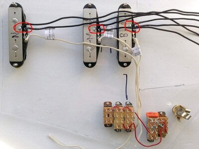
In most cases, the ground plate can be tied to the negative terminal (circled in red below), and then each negative pickup lead gets tied to a common ground point, usually the body of a pot.

Is it electrically wrong to daisy chain the pickup grounds together and just have one wire to the common ground point? I have no pots and a shared single lug for ground, so the single wire would be nice and tidy!

Ground.jpg
 
Last edited:
In most cases, the ground plate can be tied to the negative terminal (circled in red below), and then each negative pickup lead gets tied to a common ground point, usually the body of a pot.

Is it electrically wrong to daisy chain the pickup grounds together and just have one wire to the common ground point? I have no pots and a shared single lug for ground, so the single wire would be nice and tidy!

View attachment 1032161
Yep that's perfectly fine in a passive bass.
 
  • Like
Reactions: cdlynch
I followed my schematic from this post, got it all soldered on the test plexi, and OMFG IT WORKS!!!

The Lindy Fralin Strat pickups are WAY better than the weird dual rails I had, and the original Gibson pickups too, in part because they're in-line humbuckers and sound much more like single coil than standard humbuckers. They really bring it to life, and are weirdly well suited to bass with narrow string spacing (17.5 mm in this case). More clarity, and a snap it never had before. It's a much more honest sound, and no hum. As soon as I can get everything transferred to the real pickguard I'll drop a NBD post, 'cause it's nothing like the bass I bought 18 years ago. I have to do some dual amp tests with the stereo output and vintage switch. I'll post sound clips if I can do something that isn't too embarrassing.
 
  • Like
Reactions: Will_White
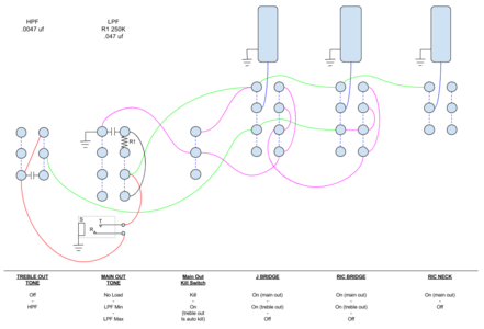
I'm making a change to the electronics. Right now I have 5.6M resistors shorting each output to ground to guard against hum when the pickups are switched off, but I'm getting crosstalk with two amps, and inconsistent performance mixing the stereo outputs with different pieces of gear. I could just sub in higher and higher value resistors, but instead I'm going to try to keep the outputs fully isolated, assuming my schematic and logic are sound.

The ideal solution would have been to use 3P3T sliders for the middle and bridge selectors, but I can't find any in the same package size as the Switchcrafts in there now. So I can use the spare lugs to make the treble output auto kill, and add a simple switch to kill the main output. Not ideal, but I'm out of options unless I want to get the pickguard recut.

So, the new schematic. I'll attempt surgery this weekend:
Gibströmbackder_SB-4353_sch_NoVol_KILLS.png
 
Last edited:
I was being a cry-baby. :)

I wonder if a laser cutter would work for general PG duties, or if it'd just melt everything... Not that I could afford that kind of setup, but it's fun to think about.

Water jet is the way to go on plastic and most metals but it's more suited to production work than one offs IMO.
panel.jpg
 
  • Like
Reactions: cdlynch
Water jet is the way to go on plastic and most metals but it's more suited to production work than one offs IMO.
panel.jpg

Very nice! Sure, any expensive machine is better suited to high volume. Also, I was just dreaming of a more complex and not even remotely rational machine that would also cut pickguard bevels in one step. That'd need a few more degrees of freedom, thus wrecking the cost/benefit ratio. I live in the land of lottery pipe dreams. It's a sad and lonely place. ;)
 
  • Like
Reactions: Dadagoboi
I'm making a change to the electronics. Right now I have 5.6M resistors shorting each output to ground to guard against hum when the pickups are switched off, but I'm getting crosstalk with two amps, and inconsistent performance mixing the stereo outputs with different pieces of gear. I could just sub in higher and higher value resistors, but instead I'm going to try to keep the outputs fully isolated, assuming my schematic and logic are sound.

The ideal solution would have been to use 3P3T sliders for the middle and bridge selectors, but I can't find any in the same package size as the Switchcrafts in there now. So I can use the spare lugs to make the treble output auto kill, and add a simple switch to kill the main output. Not ideal, but I'm out of options unless I want to get the pickguard recut.

So, the new schematic. I'll attempt surgery this weekend:
View attachment 1089632

The 5.6M resistors are gone and the new output kill wiring works perfectly, lesson learned!
 
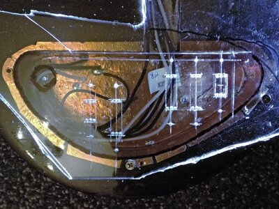
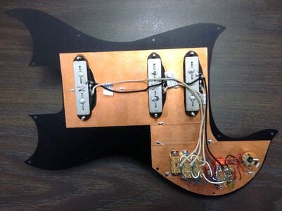
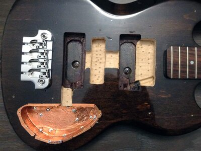
Grounding question and previously skipped guts shots! Please don't be depressed by my forstner/chisel madness!

The underside of the pickguard and the original body cavity have copper foil, and I'm thinking I should do the remaining cavities, in spite of the oddly shaped annoyance it poses.
pickguts.jpg cavities.jpg

So the grounding question: Since the bridge is grounded to the body cavity foil, and everything on the pickguard is self contained making for super easy maintenance, I wonder how I should handle the contact between the guard and body. Should I have the body foil wrap onto the top everywhere as it does now for the original cavity area, or should I pick one spot for contact?

In all places but the bottom cavity screw, firm contact is not certain, so for the rest of the would-be contact areas, there will be variable gaps, and I wonder if those could be a noise problem due to capacitance.

If there's a chance of non-perfect surface-to-surface contact causing trouble, I'll trim off the foil from the top of the body except at the lower-most screw.

Also, is it important that I treat the exposed wood somehow?

Thanks!

EDIT: This thread is stale, I'm kicking this question to Pickups and Electronics where it belongs. ;)
 
Last edited: